
Bjt emitter calculator – Unveiling the intricacies of BJT emitter calculations, this comprehensive guide empowers you with the knowledge and techniques to design and analyze BJT circuits with precision. From understanding the fundamental formula to exploring emitter resistance selection and biasing techniques, this exploration delves into the heart of BJT operation, providing a solid foundation for your electronic endeavors.
As we embark on this journey, we’ll uncover the factors that shape emitter current, unravel the role of emitter resistance, and delve into the principles of emitter-based biasing. Along the way, we’ll explore practical applications, such as emitter follower circuits, to solidify your understanding and equip you with the skills to tackle real-world challenges.
BJT Emitter Current Calculation

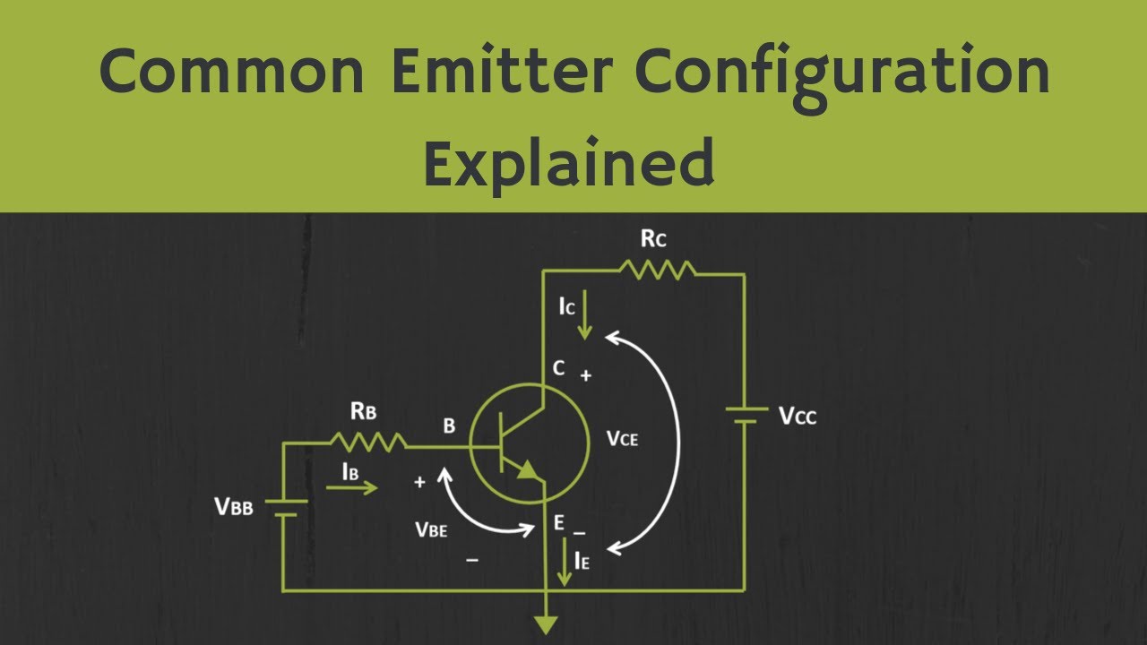
The emitter current in a bipolar junction transistor (BJT) is the current that flows from the emitter terminal to the base terminal. It is one of the three main currents in a BJT, along with the base current and the collector current.
The emitter current is controlled by the base current. When the base current increases, the emitter current also increases. This is because the base current controls the amount of minority carriers that are injected into the base region. These minority carriers then diffuse to the emitter region and become part of the emitter current.
Formula for Calculating Emitter Current
The emitter current can be calculated using the following formula:
IE= I B+ I C
where:
- I Eis the emitter current
- I Bis the base current
- I Cis the collector current
Example of Calculating Emitter Current
For example, if a BJT has a base current of 10 μA and a collector current of 200 μA, then the emitter current would be:
IE= 10 μA + 200 μA = 210 μA
Factors Affecting Emitter Current
The emitter current is affected by a number of factors, including:
- Temperature:The emitter current increases with temperature. This is because the minority carrier concentration in the base region increases with temperature.
- Transistor characteristics:The emitter current is also affected by the characteristics of the transistor itself. For example, a transistor with a high β (beta) will have a higher emitter current than a transistor with a low β.
Emitter Resistance Selection

Emitter resistance plays a crucial role in BJT circuits by providing stability and controlling the emitter current. Selecting an appropriate value for emitter resistance is essential to optimize circuit performance and prevent potential issues.
Factors to Consider
- Stability:Emitter resistance provides negative feedback, which enhances circuit stability by reducing the effects of transistor parameter variations.
- Current Control:Emitter resistance limits the emitter current by creating a voltage drop across it. This helps regulate the transistor’s operating point and prevents excessive current flow.
- Bias Point:Emitter resistance influences the transistor’s bias point by controlling the voltage at the emitter terminal. A higher resistance value shifts the bias point towards cutoff, while a lower resistance value moves it towards saturation.
Guidelines for Selection
- Rule of Thumb:A common rule of thumb is to choose an emitter resistance value that is approximately 10 times the base resistance. This provides a good balance between stability and current control.
- Specific Applications:The optimal emitter resistance value can vary depending on the specific application and transistor characteristics. For example, in high-frequency circuits, a lower resistance value may be preferred to minimize capacitive effects.
- Trade-Offs:Different emitter resistance values offer different advantages and drawbacks. Higher resistance values provide greater stability but may limit the maximum emitter current. Lower resistance values allow for higher emitter currents but may compromise stability.
Emitter-Based Biasing
Emitter-based biasing is a common technique for establishing a stable operating point for a BJT. In this configuration, the emitter terminal of the transistor is connected to a voltage source through a resistor, known as the emitter resistor (Re). The base terminal is then connected to a voltage source through a resistor, known as the base resistor (Rb).The
emitter resistor provides negative feedback, which helps to stabilize the bias point. As the collector current increases, the voltage drop across the emitter resistor increases, which in turn reduces the base current. This reduction in base current causes the collector current to decrease, thus counteracting the initial increase.
This negative feedback loop helps to maintain a relatively constant collector current over a range of operating conditions.The emitter resistor also affects the linearity of the bias circuit. A larger emitter resistor will result in a more linear relationship between the base current and the collector current.
This is because a larger emitter resistor reduces the amount of negative feedback, which allows the collector current to respond more directly to changes in the base current.
Example, Bjt emitter calculator
Consider the following example of designing an emitter-based bias circuit for a specific application:* Transistor: 2N3904
- Vcc = 12 V
- Ic = 1 mA
- Vbe = 0.7 V
Using the following formula:“`Re = (Vcc
Vbe) / Ic
“`We can calculate the value of the emitter resistor:“`Re = (12 V
0.7 V) / 1 mA = 11.3 kΩ
“`We can then select a standard resistor value that is close to this calculated value, such as 10 kΩ.The value of the base resistor can be calculated using the following formula:“`Rb = (Vcc
Vbe) / Ib
“`where Ib is the base current.Assuming a base current of 10 μA, we can calculate the value of the base resistor:“`Rb = (12 V
0.7 V) / 10 μA = 1.13 MΩ
“`Again, we can select a standard resistor value that is close to this calculated value, such as 1 MΩ.This emitter-based bias circuit will provide a stable operating point for the transistor, with a collector current of approximately 1 mA.
Emitter Follower Circuits: Bjt Emitter Calculator
An emitter follower circuit, also known as a common collector circuit, is a type of BJT amplifier circuit that provides a high input impedance and a low output impedance. This makes it useful for impedance matching, buffering, and voltage level shifting.
Operation
In an emitter follower circuit, the emitter of the transistor is connected to the output, and the collector is connected to the power supply. The base is driven by the input signal. When the input signal increases, the base current increases, which in turn increases the collector current.
However, since the collector is connected to the power supply, the collector voltage remains relatively constant. As a result, the output voltage follows the input voltage, but with a lower amplitude.
Advantages
- High input impedance
- Low output impedance
- Voltage level shifting
- Buffering
Disadvantages
- Unity gain
- Limited bandwidth
Example, Bjt emitter calculator
Consider an emitter follower circuit with the following parameters:
- Transistor: 2N3904
- Power supply voltage: 9V
- Input signal: 1V peak-to-peak
To design the circuit, we need to select the emitter resistor (Re). The value of Re can be calculated using the following formula:
Re = (Vcc
Vbe) / Ie
where:
- Vcc is the power supply voltage
- Vbe is the base-emitter voltage (approximately 0.7V for silicon transistors)
- Ie is the emitter current
For this example, we can choose Ie = 1mA. Plugging in the values, we get:
Re = (9V
0.7V) / 1mA = 8.3kΩ
Therefore, we would select an 8.2kΩ resistor for Re.
Last Point
In conclusion, mastering BJT emitter calculations is a cornerstone of electronic circuit design. By harnessing the concepts Artikeld in this guide, you’ll gain the confidence to analyze, design, and troubleshoot BJT circuits with efficiency and precision. Embrace the power of BJT emitters and unlock the full potential of your electronic creations.
